|
The small module to the left contains the CSR Bluetooth chip and related circuitry, all in a space of less than 24mm x 14mm.
82% Rating: 
|
|
|
|
Home >
Reviews >
Motherboards >
Epox 8K5A2+ |
|
|
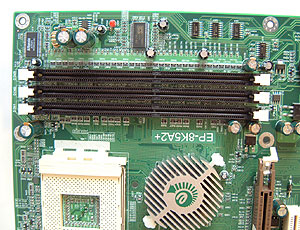
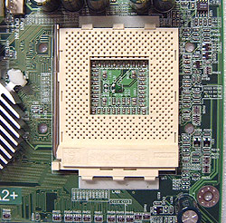
Around the Socket: Heatsink Clearances
Like the Epox 8KHA+ and 8K3A+ before it, the area next to the CPU socket on the
8K5A2+ is very spacious. You shouldn't have any problems installing too many of
those large heatsinks on this motherboard. It would be nice if more
socket A motherboards were setup with an eye towards leaving space for larger
heatsinks! With the upcoming change in socket design for AMD, and the use of a
heatsink retention mechanism these problems will fall by the wayside.... but not
for a bit.
|
pcstats heatsink clearance
measurements |
 |
Top Clearance: |
8mm |
| Bottom (cam) Clearance: |
12mm |
|
| Left Side (arm) Clearance: |
12mm |
| Right Side Clearance |
21mm |
|
| Socket Mounting Holes: |
4mm Ødia. |
| Max. Heatsink Base Dimensions (wxh): |
~82x82 mm |
|
 Note: Approx.
measurements are made from the edge of the socket (not the clips) to the
closest obstacle taller than the ZIF socket itself. The socket is 51mm
across, and 62mm from top to
bottom. Note: Approx.
measurements are made from the edge of the socket (not the clips) to the
closest obstacle taller than the ZIF socket itself. The socket is 51mm
across, and 62mm from top to
bottom.
|
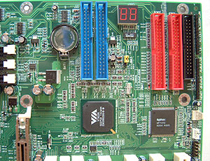
The Port80 diagnostic
LED's are a really handy tool, and one which continues to live on with the
8K5A2+. Squished in between the IDE and IDE RAID connectors, the port 80
debugging card isn't really a "card" at all, but essentially just a two digit LED
display. Depending on what numbers or characters those two LED displays are showing
you can quickly decipher possible problems with the motherboard (by referencing
the manual, Appendix E). It would be great if more manufacturers would include
this level of debugging on the board - it's an extremely useful tool when
you are trying to diagnose boot-up problems.
Epox did rearrange a few things on
the motherboard and my biggest complaint is the location of the IDE connectors. [Ed. Colin is fanatical
about this as you might have noticed. If you are an EE and do PCB
layouts for a living, PCstats.com would like to apologize, we know it can't be helped.] With
all four IDE connectors in the lower half of the motherboard, you can only
use longer or full length PCI cards in PCI slots 1 and 4.
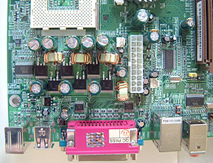
Since the Floppy drive connector is right at
the bottom of the motherboard owners of full tower cases like the Inwin Q500
may have a hard time getting the floppy ribbon cable to the top.
More Good Things and
Overclocking
In typical Epox fashion we have no less than three
fan headers to plug coolers into, with one specifically for the processor
heatsink itself. Given the number of overclockers who are used to picking up an
Epox board it would have been really nice to see at least one more fan header
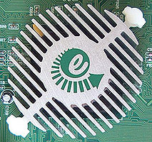
mid-board for a potential North Bridge cooling addition. But, as it stands the
VIA KT333 has one of the more unique passive heatsinks we've seen in some
time.
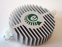 The heatsink is along the
lines of Arkua, or Thermal Integration, but does not come with a fan. Personally
speaking, while the KT333 doesn't require it for normal operation, we have
found that most boards which are heavily overclocked can always do well with a
little active cooling on the northbridge.
The heatsink is along the
lines of Arkua, or Thermal Integration, but does not come with a fan. Personally
speaking, while the KT333 doesn't require it for normal operation, we have
found that most boards which are heavily overclocked can always do well with a
little active cooling on the northbridge.
Now that
means little, and not obscene - it really isn't
necessary to strap on a large copper heatsink with 6000RPM fan to get the
job accomplished in this particular case.
A little on RAID...
IDE RAID 0 is not really considered a
true RAID since there isn't any data redundancy. RAID 0 takes two drives of the
same size/configuration and stripes them, meaning it makes one big drive out of
two equal ones. This improves performance by cutting hard drive latency in half.
Since the data is divided equally and written on two hard drives it also
increases the data bandwidth by two. The reason it's not considered true RAID is
because if one drive fails, all data is lost.
IDE RAID 1 on the other hand mirrors two
drives of the same size, so in theory if one drive fails, the other will take
over as the primary hard drive and the system can continue to operate normally.
This is what is supposed to happen with a SCSI hard drive setup and it actually
works pretty well there.
The IDE subsystem doesn't allow hard
drives to be disconnected while the computer is still powered up and in use like
SCSI can unless you have a special HDD tray. Generally, when one IDE drive fails
the system usually locks up anyway. The data is safe since it's mirrored on the
other drive which is the real benefit.
With IDE RAID 0+1, you need four
hard drives of the same configuration/size. What RAID 0+1 does is
stripes two sets of two hard drives, one set for a RAID 0 configuration and the
other for RAID 1. What this does is offer the best of both worlds, the high
performance of RAID 0, with 100% data redundancy of RAID 1. Hence the name RAID
0+1. The only downside would be the need for four identical hard drives.
|